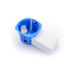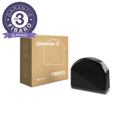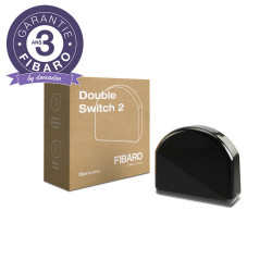
FIBARO Smart Module is designed to be installed in standard wall switch boxes or anywhere else where it is necessary to control electric devices.

Security guarantees

Shipping Policy


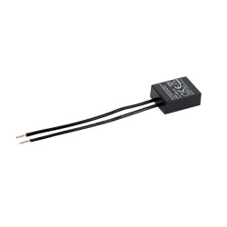
The remotely operated FIBARO Smart Module is designed to turn an electrical device or circuit on and off. The compact size of the device allows for the product to be installed in the housings of other devices. FIBARO Smart Module can be controlled either via the Z-Wave network or with a button connected directly to it.
FEATURES :
TECHNICAL DATAS :
Data sheet


Jean-Luc M. published the 26/02/2024 following an order made on 20/02/2024
Beaucoup de configurations possibles
Anonymous customer published the 09/02/2021 following an order made on 28/01/2021
Comme toujours chez fibaro, un peu cher, mais le prix s'oubli, la qualité reste
Anonymous customer published the 07/02/2021 following an order made on 22/01/2021
parfait comme tous ces modules ZWave mais vraiment chers.
Anonymous customer published the 01/02/2021 following an order made on 20/01/2021
Très pratique et procure beaucoup de souplesse avec les contacts libre de potentiel
Anonymous customer published the 27/12/2020 following an order made on 15/12/2020
Intégration facile avec Jeedom Smart. Fonctionne très bien.
Anonymous customer published the 15/10/2020 following an order made on 20/09/2020
Livraison rapide dans un colis bien emballé
Anonymous customer published the 10/08/2020 following an order made on 27/07/2020
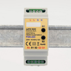
Très bon produit. Les sorties contacts secs (libre de potentiel) sont très pratique pour piloter un portail ou une porte de garage. Un plus comparé au modèle précédent : le FGS-223.
The reset procedure restores the module to its factory settings, which means that all information about the Z-Wave controller and user configuration will be deleted.
Resetting the module is not the recommended method to remove the device from the Z-Wave network. Use the reset procedure only if the primary controller is missing or inoperative.
1. Press and hold the maintenance button to access the menu.
2. Release the button when the module LED turns yellow.
3. Quickly press the button to confirm.
4. After a few seconds, the module will be restarted, which is signaled by a red LED.
The FGS-214 and FGS-224 modules have an integrated Z-Wave network main controller range tester.
To make the Z-Wave range test possible, the module must be included with the Z-Wave controller. The tests can stress the network, so it is recommended to perform the test only in special cases.
To test the main controller's range:
1. Press and hold the maintenance button to access the menu.
2. Release the button when the device turns magenta.
3. Quickly press the button to confirm.
4. The visual indicator will indicate the range of the Z-Wave network (range signaling modes described below).
5. To exit the Z-Wave range test, short press the button.
Z-Wave Range Tester Signaling Modes:
Visual indicator flashing green - the device is attempting to establish direct communication with the main controller. If a direct communication attempt fails, the device will attempt to establish routed communication, via other modules, which will be indicated by a visual indicator flashing yellow.
Bright green visual indicator - the device communicates directly with the main controller.
Visual indicator flashing yellow - the device is trying to establish routed communication with the main controller via other modules (repeaters).
Bright yellow visual indicator - the device communicates with the main controller via the other modules. After 2 seconds, the device will retry to establish direct communication with the main controller, which will be indicated by a visual indicator flashing green.
Visual indicator flashing purple - device is communicating at the maximum distance of the Z-Wave network. If the connection is successful, it will be confirmed with a yellow glow. It is not recommended to use the device at the limit of range.
Glowing visual indicator - the device cannot connect directly to the main controller or through another Z-Wave network device (repeater).
To remove the module from the Z-Wave network:
1. Power up the module.
2. Put the main controller in exclusion mode (see controller manual).
3. Quickly press the maintenance button three times.
4. The LED will start flashing yellow, wait for the deletion process to complete.
5. Successful exclusion will be confirmed by Z-Wave controller message and red LED color.
To add the module to your Z-Wave network manually:
1. Power up the module.
2. Put the main controller in inclusion mode (Secure / Non-Secure Mode) (see controller manual).
3. Quickly three times press the button connected to S1/S2 or the maintenance button.
4. The LED will start flashing yellow, wait for the inclusion process to complete.
5. If you are performing a secure inclusion, enter the underlined part of the DSK (label at the bottom of the box).
6. Inclusion will be confirmed by Z-Wave controller message and LED:
Green - passed (unsecured, S0, S2 unauthenticated),
Magenta - passed (Security S2 authenticated),
Red - not successful.
To add the module to the Z-Wave network using SmartStart:
1. To use SmartStart, your controller must support Security S2 (see controller manual).
2. Enter the full DSK code into your controller. If your controller is able to scan a QR code, scan the QR code placed on the box or label of the device.
3. Power up the module.
4. Wait for the inclusion process to start (may take a few minutes), which is signaled by the yellow LED flashing.
5. Inclusion will be confirmed by Z-Wave controller message and LED:
Green - passed (unsecured, S0, S2 unauthenticated),
Magenta - passed (Security S2 authenticated),
Red - not successful.
You might also like
FIBARO Smart Module is designed to be installed in standard wall switch boxes or anywhere else where it is necessary to control electric devices.